TM 1-1270-476-30
4-240
4-29. CONTROL PANEL ASSEMBLY 2A1 REPAIR (cont)
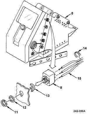
f. Remove switch S3 (8) by removing jamnut
(11), lockwasher (12) and modified keyway
washer (13).
g. Cut lacing and tying tape (14) as necessary
to provide enough wire slack for component
replacement.
h. Tag and unsolder wires (15).
INSTALLATION
i. Solder wires (15) to replacement switch S3
(8).
j. Install switch S3 (8) with modified keyway
washer (13), lockwasher (12), and modified
jamnut (11). Ensure that modified keyway
washer seats in notch on control panel
housing.
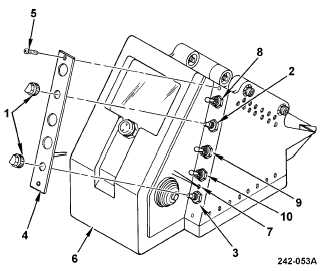
k. Feed panel wires (7) into housing and
install illuminated panel assembly A2 (4)
with two screws (5).
l. Install knob assemblies (1) on shafts of
resistor R4 (2) and resistor R5 (3) and
tighten setscrews.
m. Route wires along wire bundle install lacing
and tying tape as required to secure wire
bundle.
n. Have installation inspected.
o. Install HOD assembly (1 above).
END OF TASK


