TM 1-1270-476-30
4-181
4-12. DAY SENSOR SUBASSEMBLY REPAIR (cont)
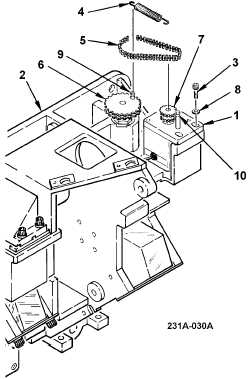
10. POSITIVE DRIVE BELT REPLACEMENT
REMOVAL
a. Loosen optics motor assembly (1) on No. 3
optical assembly housing (2) by loosening
two screws (3).
b. Remove spring (4) and positive drive belt
(5).
INSTALLATION
c. Remove old corrosion inhibitive sealing and
coating compound from mounting hardware
(para 2-6).
d. Apply corrosion inhibitive sealing and
coating compound to two screws (1) (para
2-6). Use class 1A application.
NOTE
Before installing positive drive belt on sprocket
wheel turn sprocket wheel CCW approximately
150°.
e. Install positive drive belt (5) on sprocket
wheel (6) and optics motor assembly
sprocket (7).
f. Secure optics motor assembly (1) to No. 3
optical assembly housing (2) using two
screws (3) with flat washers (8).
g. Install spring (4) on pin (9) on sprocket
wheel and pin (10) on optics motor
assembly.
NOTE
Sprocket wheel height adjustment is
accomplished using two jam nuts located
under sprocket wheel.
h. Verify sprocket wheel (6) and optics motor
assembly sprocket (7) are level to within
0.062 inches. Adjust as required.
END OF TASK