TM 55-1660-320-23 & P
3-36. WINCH ASSEMBLY - REPAIR (cont)
3-36
i.
j.
k.
1.
m.
Inspect identification and lubrication plates for legibility and security of attachment.
Inspect limit switch drive assembly and motor assembly for damage. Check for signs of overheating and shorting.
Inspect boot and motor air duct for cuts and deterioration.
Inspect cable hook in accordance with Task 2-56.
Inspect hoist cable in accordance with Task 2-59.
4.
5.
Repair. Repair of parts is limited to the removal of minor nicks, burrs, scratches or other surface damage using aluminum
oxide cloth or fine abrasive. Clean pans thoroughly after repair. If damage is extensive, or if minor repair will affect
serviceability, replace the part.
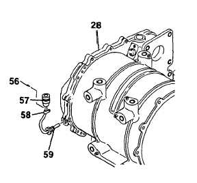
Reassembly.
a.
b.
c.
Screw thermal switch (59) into winch housing
(28). Install electric braid and heat shrink
tubing on leads of switch.
Using a suitable pin installation tool, instaIl
pins into connector (57). Twist ends of electric
braid to secure and shrink heat shrink tubing
in place.
Install clamp (56) onto connector (57) using
screws (58).
GO TO NEXT PAGE
3-120