TM 55-1680-320-23 & P
2-26. MICROSWITCH ASSEMBLY (FULL UP) - TEST
2-26
This task covers: Testing
INITIAL SETUP
Personnel Required:
Equipment Condition:
67N, UHl Helicopter Repairer
Hoist installed in helicopter
67T, UH60 Helicopter Repairer
Parts/Materials
Equipment Condition Para:
None
Task 2-5
Tools and Test Equipment:
References:
Tool Kit, Aircraft Mechanic
None
NSN 5180-00-323-4692
Ground Power Unit (GPU)
1.
2.
3.
4.
5.
6.
Apply power to hoist. Position HOIST PWR switch
to ON.
Move control pendant switch to DWN. Reel out
approximately 4 feet (12.19 dm) of cable.
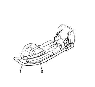
Ensure actuator arm (1) moves freely without bind-
ing through full range.
Ensure distance between lowered actuator arm (1)
and bottom of cable guide (2) is 0.75 inch (1.91
cm). Adjust as required (Task 2-24).
Slowly move control pendant switch to UP position
and reel in cable. Ensure cable hook contacts with
actuator arm stops hoist before fully compressing
cylinder.
Repeat test several times to ensure proper operation.
FOLLOW-ON MAINTENANCE:
None
END OF TASK
2-67