TM 55-1680-320-23 & P
2-24. ACTUATOR ASSEMBLY (UP LIMIT) - ADJUST
2-24
This task covers: Adjustment
INITIAL SETUP
Personnel Required:
67N, UH1 Helicopter Repairer
67T, UH60 Helicopter Repairer
Equipment Condition:
Hoist installed in assembly stand
Parts/Materials:
Equipment Condition Para:
None
Task 2-5
Tools and Test Equipment:
Reference:
Tool Set, Aviation Unit Maintenance
None
NSN 4920-00-567-0476
1.
2.
3.
4.
5.
6.
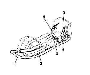
Using a measuring device, check that the distance
between lowered arm of actuator assembly (1) and
bottom of cable guide (2) is 0.75 inch (1.91 cm).
Bend large tang (3) at rear plate of actuator (1)
to achieve 0.75 inch (1.91 cm) clearance.
Press up on actuator arm (1) until small tangs (4)
engage microswitch assemblies(5). Audibly check
that both switches engage at same time.
Bend small tangs (4) as required to coordinate
switch engagement.
Press up on actuator arm (1) to engage switches
(5). Using measuring device, check that distance
between top of arm and cable guide (2) is 0.44
inch (1.18 cm).
Bend small tangs (4) to achieve 0.44 inch (1.18
cm) clearance.
FOLLOW-ON MAINTENANCE:
Test microswitch assembly
(Task 2-26)
END OF TASK
2-65