TM 55-1680-320-23 & P
2-29. BOOM POSITION SUPPORT ASSY - ADJUST
2-29
This task covers: Adjustment
INITIAL SETUP
Personnel Required:
Equipment Condition:
67N, UH1 Helicopter Repairer
Hoist installed in helicopter
67T, UH60 Helicopter Repairer
Parts/Materials:
Equipment Condition Para:
Lockwire (Item 17, App. D)
Task 2-5
Locktite Compound (Item 16, App. D)
Tools and Test Equipment:
Reference:
Tool Kit, Aircraft Mechanic
None
NSN 5180-00-323-4692
1.
2.
3.
4.
5.
Simulate helicopter floor positions STA 82.05 and
BL 35.10 and mark as follows:
a. Mark a line 10 inches long out from stud along
station line 82.05.
b. Mark a line 10 inches long aft from stud along
butt line 35.10.
Ensure AIRCRAFT POSITION switch is in posi-
tion 1-3 and boom position actuator is locked in
position 1.
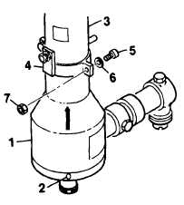
Release base cover (1) by removing screws (2).
Slide cover upon stanchion tube (3) to gain access
to boom position switches.
Remove stud ring (4) be removing bolts (5), wash-
ers (6) sod nuts (7).
Apply electrical power to helicopter and position
HOIST PWR switch to ON.
GO TO NEXT PAGE
2-71