
TM 1-1740-221-13&P&P
FIELD MAINTENANCE
CREW PROTECTION SYSTEM (CPS) WIRING HARNESS
INITIAL SETUP:
Tools and Special Tools
References
Tool Kit, General Mechanic (WP 0157, Item 24)
Personnel Required
Light Wheel Vehicle Mechanic91B - 1
REMOVAL
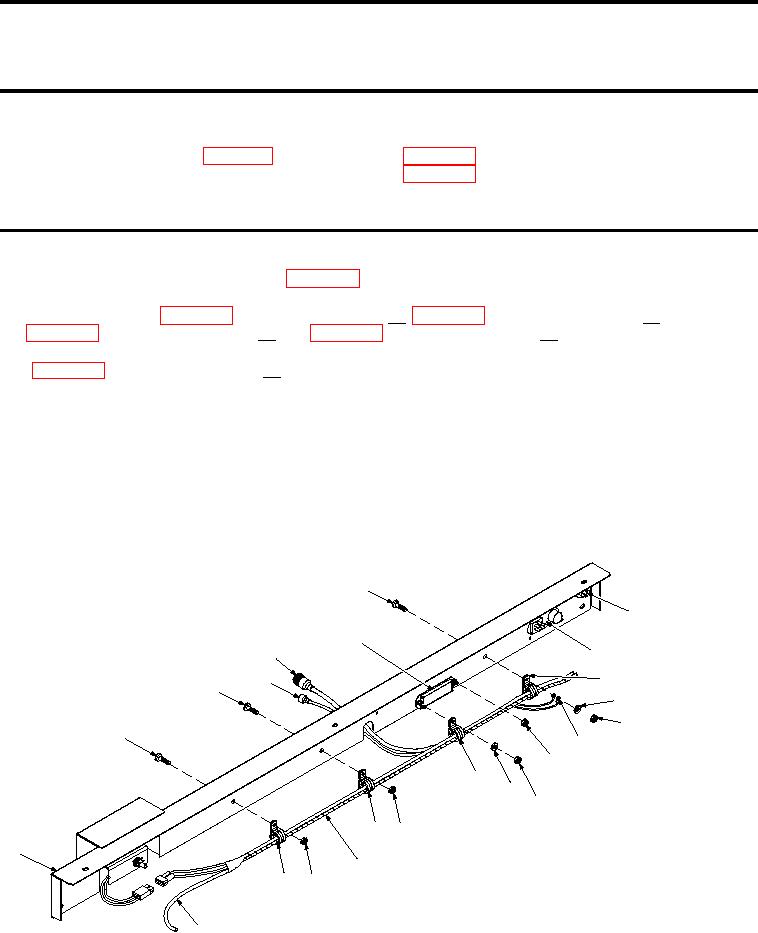
1. Remove CPS Dash (Figure 1, Item 1)(WP 0098).
2. Disconnect wires from Wiper/Washer Switch (W/W SW), Fan Control Switch (FC SW), and Auxiliary
3. Disconnect CPS Wiring Harness (W/H) connector from Temperature Control Diode (TCD) connector
(WP 0098, DISASSEMBLY, Step 2a).
4. Remove screw (Figure 1, Item 7), harness clamp (Figure 1, Item 10), two ground wires (Figure 1, Item
13), lat washer (Figure 1, Item 11), and nut (Figure 1, Item 12) between Heater Control Panel (HCP)
(Figure 1, Item 9) and AFB (Figure 1, Item 6).
5. Remove nut (Figure 1, Item 15), harness clamp (Figure 1, Item 17), and lat washer (Figure 1, Item 16)
from R/H side of AFB (Figure 1, Item 6).
6. Remove two screws (Figure 1, Item 2 and 3), two nuts (Figure 1, Item 18 and 21), and two harness clamps
(Figure 1, Item 19 and 22) between AFB (Figure 1, Item 6) and wiper motor cut-out.
7. Remove all tie-straps securing washer tubing (Figure 1, Item 23) to CPS W/H (Figure 1, Item 20).
8. Remove CPS W/H (Figure 1, Item 20).
7
8
6
9
5
10
4
3
11
12
2
13
14
17
16
15
19 18
1
20
22
21
23
SATSCPSab0014
Figure 1.
CPS Wiring Harness
END OF TASK
01081