
0065
TM 1-1740-221-13&P&P
FUEL SYSTEM SERVICING - (CONTINUED)
4.
Install two ittings (Figure 2, Item 5) in the same position as previously removed.
5.
Remove hose plugs and connect hoses (Figure 2, Item 2 and 10) and secure with clamps (Figure 2, Item 4).
6.
Install new ilter (Figure 2, Item 9) onto bowl ensuring seal is in the bowl housing slot and hand tighten.
7.
Fill fuel ilter/bowl assembly with fuel and lubricate ilter seal with clean fuel.
8.
Spin fuel ilter/bowl assembly onto housing (Figure 2).
9.
When fuel ilter/bowl assembly seal contacts the mating surface tighten by hand an additional turn.
10.
Install fuel heater wiring (Figure 2, Item 6) onto bowl receptacle connector.
11.
Perform air bleeding the fuel system this Work Package.
12.
Connect battery cable (WP 0111).
END OF TASK
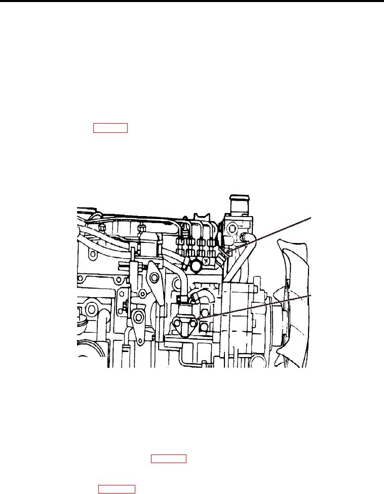
AIR BLEEDING THE FUEL SYSTEM
1
2
WP0056F3
Figure 3. Injector Pump Air Bleed Valve
1.
Ensure fuel tank has an adequate amount of fuel.
2.
Open Injector Pump air bleed valve (Figure 3, Item 1).
3.
Pump or push fuel/water separator plunger (Figure 2, Item 3) twenty times.
4.
Close Injector Pump air bleed valve (Figure 3, Item 1).
5.
Connect battery chassis negative cable (WP 0111).
6.
Remove and clean drip pan.
7.
Perform Maintenance Operation Check (no leaks).
8.
Install center deck plate (WP 0028).
00655