
TM 1-1730-215-13&P
FIELD MAINTENANCE
MAINTENANCE PLATFORM ADJUSTABLE, AIRCRAFT
(TYPE B-4A) PART NO. 54J6345 NSN 1730-00-294-8883
MAIN FRAME ASSEMBLY
INITIAL SETUP:
References
Equipment Condition
Platform Assembly - Handrail removed (WP 0012 00)
Platform - Ladders removed (WP 0013 00)
Scissors Assembly removed (WP 0014 00)
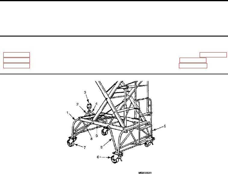
Figure 1.
Main Frame Assembly.
INSPECTION OF INSTALLED ITEMS
Inspect the main frame for cracks or other damage and repair or replace as necessary.
REMOVAL
1.
After removal of upper assemblies, turn lower assembly top side down.
2.
Remove bolts securing the four leg braces (Figure 1, Item 8) to main frame (Figure 1, Item 9).
3.
Remove bolts attaching front legs (Figure 1, Item 1) to main frame and remove front legs (Figure 1, Item 1),
tow bars (Figure 1, Item 2 and 4), platform bar (Figure 1, Item 3) and front casters (Figure 1, Item 7).
4.
Remove bolts attaching rear legs (Figure 1, Item 5) to main frame and remove rear legs (Figure 1, Item 5)
and rear casters (Figure 1, Item 6).
INSTALLATION
1.
Attach rear legs (Figure 1, Item 5) and rear casters (Figure 1, Item 6) to rear of main frame (Figure 1, Item 9)
using bolts previously removed in REMOVAL, Step 4
2.
Attach rear leg braces (Figure 1, Item 8) to sides of main frame using bolts previously removed in REMOVAL,
Step 2
3.
Attach front legs (Figure 1, Item 1), front casters (Figure 1, Item 7) and tow bars (Figure 1, Item 2 and 4) and
platform bar (Figure 1, Item 3) to the front end of the main frame.
0015 00-1