
TM 1-1730-201-13&P
OPERATOR INSTRUCTIONS
MAINTENANCE PLATFORM, TYPE B-1
PART NO. 50-19080 NSN 1730-00-390-5618 EIC: NA
CONTROLS AND INDICATORS
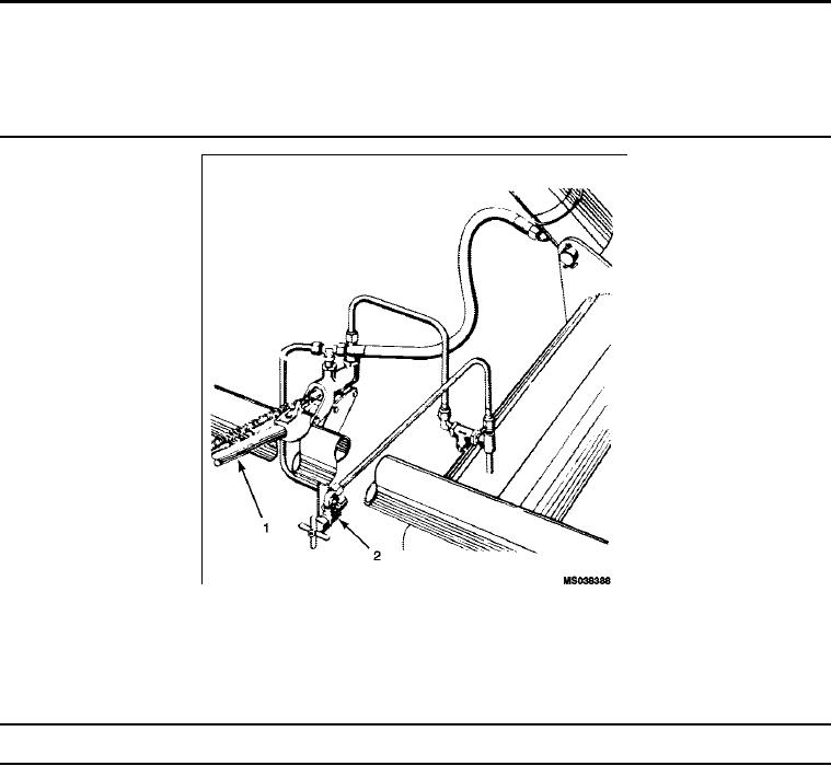
Figure 1.
Hand Pump, Fluid Strainer, and By-Pass Valve.
Table 1. Maintenance Platform Controls and Indicators.
Control/Indicator
Function
Key
Hand Pump Handle
When actuated by the handle, the hydraulic hand pump draws hydraulic
1
uid from the reservoir and forces the uid into the hydraulic cylinder
assembly causing the upper structure to rise.
By-Pass Valve
The by-pass valve is a needle-type valve and is located under the
2
hydraulic hand pump. When the by-pass valve is in the closed position,
it locks the uid under pressure in the hydraulic cylinder assembly.
Opening the by-pass valve allows the uid from the cylinder assembly
to by-pass the hand pump and return to the reservoir, causing the upper
structure to lower.
0004 00-1