
TM 1-1500-204-23-11
(2) Stacking Sequence. Ply must be laid down
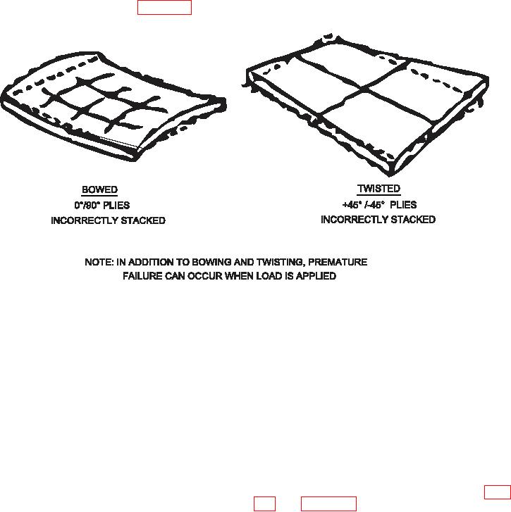
a few examples of stacking sequence effects on a lat
(stacked) in the proper sequence. Incorrectly stacked
laminate. In general, the upper half of the laminate
ply can result in warped or bowed panels and prema-
should be a mirror image of the lower half.
ture failure when load is applied. Figure 5-11 provides
Figure 5-11. Stacking Sequence Effects
(3) Orientation Markings. Orientation mark-
viewed from one side; or it may show cross sections
ings are essential to proper repair ply layup. The
as referenced from the center of the structure or from
orientation marks used in this chapter may or may not
outer mold line to inner mold line. Technicians must
be used for the ply layup templates. When the repair
understand the orientation coordinate system used. If
information calls out the orientation angle of each ply,
no established orientation system is available, users
you must use the same coordinate system used by
must establish a coordinate system.
the engineers to design the repair; this information
is found in the system speciic technical manual,
f. Ply Cutting Template Manufacture. The irst
repair drawings or Original Equipment Manufacturer
element of patch preparation is generating a visual
(OEM) drawings. If you are reading the laminate
aid in the form of a patch drawing or sketch. It
to determine the orientation angle of each ply, and
should include a coordinate system showing ply orien-
have no guidance from the sources listed above, you
tation and shape, nearby fasteners, prominent aircraft
should orient the 0 degree direction of your coordinate
features, and overall dimensions of damage cutout,
system along one of the iber directions, usually the
scarf, and repair plies. An example is shown in igure
iber direction running the length or width of the part.
5-12 and igure 5-13. Manufacture the template from
suitable acetate, Mylar or other wax free material.
(4) Drawing Orientation. Drawings may show
ply layup orientation for the entire structure as if it were