
TM 1-1500-204-23-11
damage lies in a nonrepairable zone, the part must
map provides an aid when performing subsequent NDI
be forwarded to depot for disposition.
of the area after damage removal and after repair as
well as providing a permanent record of the defect
indications. Follow these steps to create a defect
d. Reevaluate. Following damage removal, rein-
map.
spect the damage area to ensure all the damage
was in fact removed. Current NDI methods used to
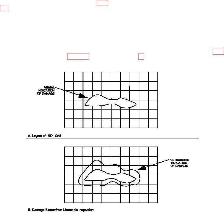
(1) Using the visual indication of damage as a
detect subsurface delaminations are capable of only
guide, mark a grid of 0.5 inch squares out to
inding the irst delamination nearest the surface on
a point at least 1 inch away from the edge
which the probe was applied. Deeper delaminations
of the damage on the part surface using a
can be masked by the irst delamination (see igure
marking pen.
5-2, View D). When the opposite side is accessible
a secondary inspection can be performed to deter-
mine the existence of additional delamination. After
(2) Using one of the ultrasonic techniques listed
removing what initially appears to be all the dam-
above; inspect each 0.5 inch square of the
age present, it is necessary to re-inspect the area to
marked grid.
ensure no delaminations remain below the originally
deined damage.
(3) Mark the location of defect indications (and
depths if using the pulse-echo ultrasonic
e. Defect Mapping. The defect map is used to
technique) as indicated on the CRT on the
determine the damage layout and extent of material
part surface using a marking pen (see igure
to be removed as described in Chapter 6. A Mylar
Figure 5-5. Defect Mapping of Damage Extent from NDI