
TM 1-1500-204-23-11
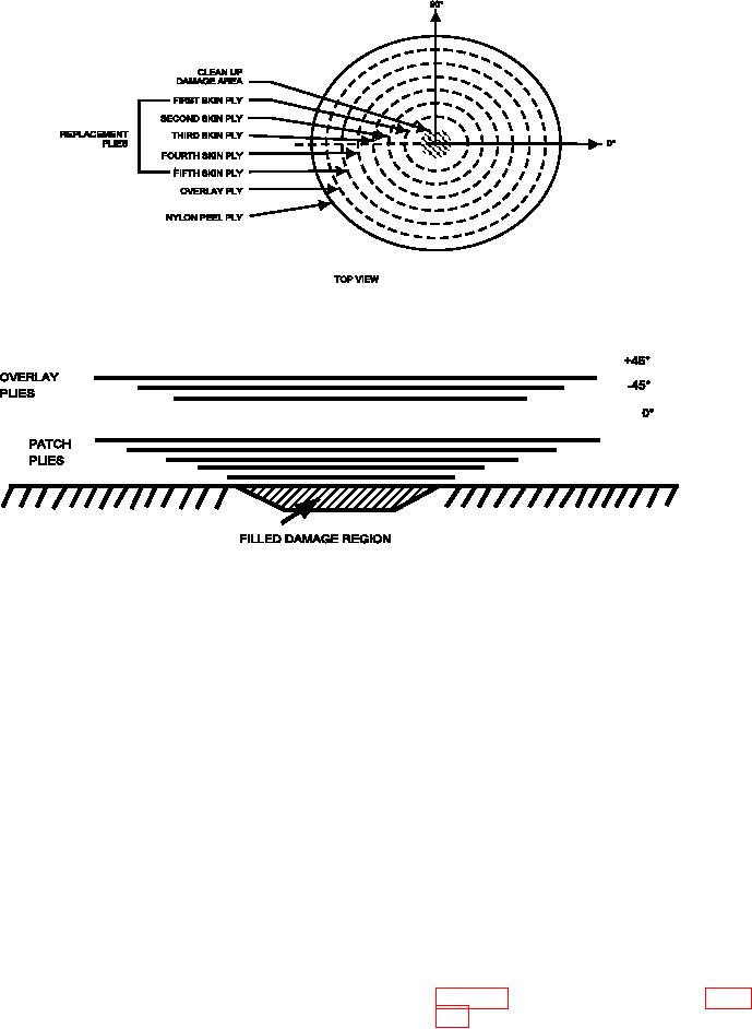
Figure 5-12. Patch Drawing Example and Typical Scarf Repair Stackup (Sheet 2 of 2)
Figure 5-13. Scab Patch Ply Arrangement
NOTE
(2) Determine part 0 degree and other ply direc-
tions as speciied in the system speciic tech-
An intermediate template from vacuum bag
nical manual and mark on part near repair
is not required if the part is relatively lat
area.
and 0.040 inch thick acetate will conform to
surface.
(3) Tape a piece of 0.002 inch thick vacuum bag
Ensure patch templates used for layup and
ilm over the part in the repair area. Slice
alignment match the orientation and reference
bag ilm as required to prevent wrinkling over
lines on the structure being repaired include
contoured areas.
ply orientation and stacking sequence on all
drawings and templates.
(4) Place the bag ilm containing the ply periph-
ery trace on a lat surface.
(1) Determine the number of plies, ply orienta-
tions and the ply stacking sequence from the
(5) Place the acetate over the bag ilm and mark
system speciic technical manual. Deter-
ply cutting line(s) on the acetate from the
mine the size of the plies from the system
ply periphery trace(s). Include ply number,
speciic technical manual. For patches,
orientation, and zero iber reference.
determine ply size based upon the dam-
age cleanup hole shape and required patch
(6) Cut the acetate along the ply cutting line
overlap. Refer to the system speciic tech-
using scissors. The acetate will be used in
nical manual for guidance on determining
patch overlap requirements. Mark the ply
5-14 shows a typical example.
periphery on the part surface.