TM 1-1270-476-30
4-58
4-5. NIGHT SENSOR ASSEMBLY (NSA) REPAIR (cont)
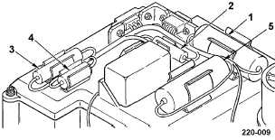
3. CAPACITOR C1 THRU C5 REPLACEMENT
WARNING
Before performing maintenance/repair,
discharge all high-voltage capacitors (para
2-4).
NOTE
This procedure is for replacing any of the
following:
Capacitor C1 (1)
Capacitor C4 (4)
Capacitor C2 (2)
Capacitor C5 (5)
Capacitor C3 (3)
REMOVAL
a. Cut lacing and tying tape spot ties as
necessary to access hot air shrinkable
splice connecting the capacitor lead wires
and chassis wires.
b. Cut chassis wire at the point where wires
enter hot air shrinkable splices.
c. Remove capacitor from spring tension clip
and discard.
INSTALLATION
d. Install capacitor in spring tension clip.
NOTE
Capacitor wires and chassis wires must be
long enough to overlap inside solder band of
hot air shrinkable splice. Thermoplastic inserts
of splice, when shrunk, must grip chassis wire
insulation and insulation tubing.
e. Cut capacitor wires to length required for
connection using hot air shrinkable splices.
f. Strip insulation from chassis wire ends.
g. Tin capacitor and chassis wire ends.
h. Install insulation tubing on capacitor lead
wires. Trim insulation tubing to allow
sufficient length to extend into splices.
i. Insert capacitor and chassis wire ends in
hot air shrinkable splice.
CAUTION
When applying heat to hot air shrinkable
splice, take care to avoid damaging
components.
j. Using heat gun with reflector, shrink hot air
shrinkable splice.
k. Position capacitor and chassis wires in
chassis wire bundle and spot tie with lacing
and tying tape.
l. Have installation inspected.
END OF TASK