TM 55-1680-320-23&P
Change 8 2-129
2-60. HOIST CABLE ASSEMBLY - REPLACE (cont)
2-60
g. Connect 28 vdc to hoist.
h. Position control pendant switch to UP. Reel in
cable until five to seven wraps are visible on
drum
i. Move control pendant switch to DWN. Reel out
cable until SW1 switch actuates and stops
motor. Three wraps shall be visible on drum
j. Adjust limit switch drive assembly as required
(Task 2-54)
k. Ensure cable does not rub on sides of cable
cutter barrel. Adjust as required by aligning the
winch assembly (Task 2-47)
l. If required, install heat shrinkable sleeving with
a 3/8 inch inside diameter 3 - 4 inch long) onto
hook end of cable assembly as follows:
(1) Lubricate swaged ball on hook end of
cable. Slide tubing over swaged ball and
align tubing with the end of shank on ball.
(2) Heat shrink tubing tightly in place in accor-
dance with TM 55-1500-323-24
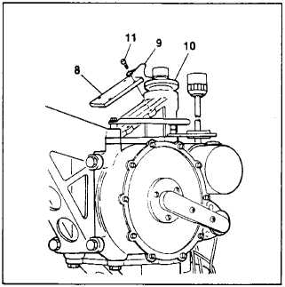
m. Install cover plate (8) and lanyard (9) to upper
support (10) using screws (11).
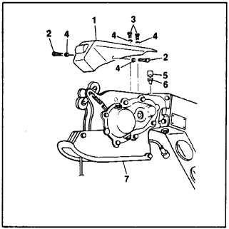
n. Install anvil (6) and cable cutter cap (5).
o. Install pressure roller cover (1) using screws
(2, 3) and washers (4).
FOLLOW-ON MAINTENANCE:
Install cable hook assembly
(Task 2-58)
Conduct performance check
(Task 2-7)
END OF TASK