TM 55-1680-320-23 & P
2-29. BOOM POSITION SUPPORT ASSY - ADJUST (cont)
2-29
8.
f. Move HOIST PWR switch to ON. Move BOOM switch to IN, then OUT positions.
g. Check boom travel to ensure proper adjustment of switch (10) and cam (8). Repeat steps a. through e. as required.
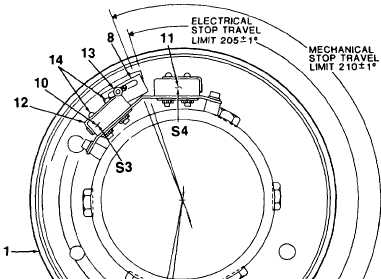
Move Boom switch to IN position (CW). Cam (9) should be under roller leaf actuator of switch (11). Boom head
assembly shall be in line with BL 35.10 mark. Adjust switch and cam as follows:
a.
b.
c.
d.
e.
f.
g
Move HOIST PWR switch to OFF.
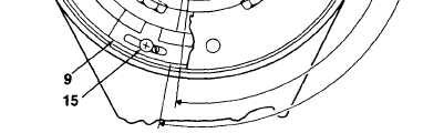
Loosen screw (15). Move cam (9) towards switch (10) for over-travel, away from switch for under-travel
Apply locktite compound to threads of screw (15). Tighten screw.
Top of cam (9) should depress actuator and just close switch (11).
If further adjustment is required, loosen screws (14) and reposition switch (11). Tighten screws.
Move HOIST PWR switch to ON. Move BOOM switch to OUT, then IN positions.
Check boom travel to ensure proper adjustment of switch (11) and cam (9). Repeat steps a. through e. as required.
REACTION ARM AND UPPER
BASEPLATE LOCKED IN
POSITION NO. 1
TOP VIEW
GO TO NEXT PAGE
2-73