TM 55-1680-320-23 & P
2-20. BOOM HEAD ASSEMBLY - REPLACE (cont)
2-20
2. Installation.
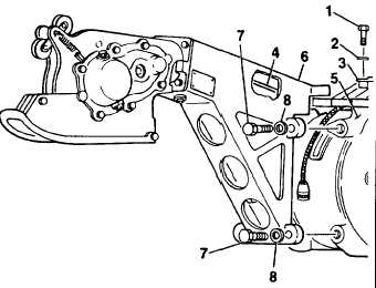
a. Lift up on upper support assembly to allow
clearance for flexible drive shaft (4) during
boom head installation.
b. Position boom head assembly (6) against winch
(5). Secure using bolts (7) and washers (8).
c. Torque bolts (7) to 160-190 in.lbs.
d. Connect flexible drive shaft (4) to winch (5).
e. Swing handle (3) inboard and position. Tighten
rear bolts (1) and install front bolts and washers
(2).
Torque bolts (1) to 160-190 in.lbs.
Connect electrial harnesses.
FOLLOW-ON MAINTENANCE:
Install cable
(Task 2-60)
Service boom head assembly
(Task 2-18)
conduct performance check
Task 2-7)
END OF TASK
2-60
f .
g.

