0026 00
TM 1-1730-227-13&P
REMOVAL
1.
Pull brake drum (Figure 1, Item 7) and hub assembly (Figure 1, Item 6) off the brake assembly (Figure 1, Item
4).
2.
Remove four hex head cap screws (Figure 1, Item 5), lock washers (Figure 1, Item 3), and plain hex nuts
(Figure 1, Item 2) securing the brake assembly (Figure 1, Item 4) to the rear axle. Remove the brake assem-
bly (Figure 1, Item 4).
INSTALLATION
1.
Position the brake assembly (Figure 1, Item 4) on the rear axle (Figure 1, Item 1) and align holes.
2.
Install the four hex head cap screws (Figure 1, Item 5) through the brake assembly (Figure 1, Item 4) and
place a lock washer (Figure 1, Item 3) and a plain hex nut (Figure 1, Item 2) on each hex head cap screw
(Figure 1, Item 5). Tighten plain hex nuts (Figure 1, Item 2) to a torque of 19 ft-lbs.
3.
Position the brake drum (Figure 1, Item 7) and hub assembly (Figure 1, Item 6) on the brake assembly (Figure
1, Item 4) after installing WP 0025 00, Hub and Bearings.
DISASSEMBLY
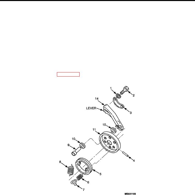
Figure 2.
Parking Brake Exploded View.
1.
Remove two screws (Figure 2, Item 2) and two lock washers (Figure 2, Item 1) to loosen the sector (Figure 2,
Item 3) from the back of the mounting plate (Figure 2, Item 11). Note the position of the sector (Figure 2, Item
3) and the pedal assembly (Figure 2, Item 14) for reassembly.
2.
Loosen screw (Figure 2, Item 2) and remove the pedal assembly (Figure 2, Item 14) along with the sector
(Figure 2, Item 3).
3.
Turn the mounting plate (Figure 2, Item 11) over and push in on the clip (Figure 2, Item 7). Pull the spring pin
(Figure 2, Item 4) free from the back of the mounting plate (Figure 2, Item 11) and remove the compression
spring (Figure 2, Item 6) and clip (Figure 2, Item 7) from the front of the mounting plate (Figure 2, Item 11).
0026 00-2

