
0020 00
TM 1-1730-227-13&P
ADJUSTMENT CONTINUED
TIE ROD ADJUST PROCEDURE
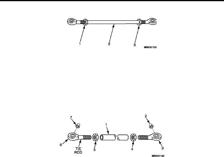
Figure 6.
Tie Rod Assembly.
1.
If measurement B (Figure 5 ) is too short, lengthen tie rods. If measurement is too long, shorten tie rods as
needed.
2.
Loosen two locknuts (Figure 6, Item 1 and 3) on both tie rods.
3.
Turn tubes (Figure 6, Item 2) to shorten or lengthen as needed.
4.
Check the adjustments using the Check Adjustment Procedure.
5.
When measurements are correct, tighten locknuts (Figure 6, Item 1 and 3).
DISASSEMBLY
Figure 7.
Tie Rod Exploded View.
NOTE
Take note that there are left and right-hand threaded hex jam nuts and tie rod ends.
1.
Loosen two hex jam nuts (Figure 7, Item 4 and 5) on the tie rod ends (Figure 7, Item 3 and 6).
2.
Unthread two tie rod ends (Figure 7, Item 3 and 6) with hex jam nuts (Figure 7, Item 4 and 5) from the tie rod
steering body (Figure 7, Item 1).
3.
Unthread and discard grease fittings (Figure 7, Item 2 and 7) from each tie rod end (Figure 7, Item 3 and 6) if
damaged.
ASSEMBLY
1.
Thread two tie rod ends (Figure 7, Item 3 and 6) with hex jam nuts (Figure 7, Item 4 and 5) into the tie rod
steering body (Figure 7, Item 1).
2.
It will be necessary to make adjustments in the tie rod assembly for proper alignment of tires during installa-
tion. Refer Tie Rod Adjust Procedure above.
3.
Install new grease fittings (Figure 7, Item 2 and 7) in the tie rod ends (Figure 7, Item 3 and 6) if damaged
fittings were removed.
END OF WORK PACKAGE
0020 00-4