
TM 1-1730-227-13&P
0020 00
INSTALLATION
LEFT SIDE
1.
Position one end of the tie rod (Figure 3, Item 3) on the left hand axle and king pin pivot assembly (Figure 3,
Item 5) and the other end on the bottom of the tongue assembly and install two bolts (Figure 3, Item 4).
2.
Install two flat washers (Figure 3, Item 6) and slotted hex nuts (Figure 3, Item 1) on bolts (Figure 3, Item 4).
Thread the slotted hex nuts (Figure 3, Item 1) on the bolts (Figure 3, Item 4) far enough to install new cotter
pins (Figure 3, Item 2) through slots in the slotted hex nuts (Figure 3, Item 1) into the hole in the bolts (Figure
3, Item 4).
3.
Bend the open end of the cotter pins (Figure 3, Item 2) to secure them in place.
4.
Check and adjust tie rod as necessary.
RIGHT SIDE
1.
Position one end of the tie rod (Figure 4, Item 6) on the right hand axle and king pin pivot assembly (Figure 4,
Item 2) and the other end on the top of the tongue assembly and install two bolts (Figure 4, Item 1).
2.
Install two flat washers (Figure 4, Item 3) and slotted hex nuts (Figure 4, Item 4) on bolts (Figure 4, Item 1).
Thread the slotted hex nuts (Figure 4, Item 4) on the bolts (Figure 4, Item 1) far enough to install new cotter
pins (Figure 4, Item 5) through the slots in the slotted hex nuts into the hole in the bolts (Figure 4, Item 1).
3.
Bend the open end of the cotter pins (Figure 4, Item 5) to secure them in place.
4.
Check and adjust tie rod as necessary.
ADJUSTMENT
CHECK ADJUSTMENT PROCEDURE
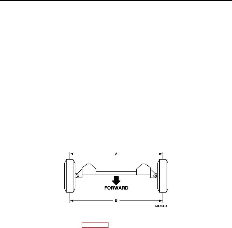
Figure 5.
Tie Rod Adjustment Measurements.
1.
Adjust wheel bearings. Refer to WP 0025 00, Hub and Bearings. Place trailer on level ground or floor.
2.
Position tow bar so that both front tires are straight, so that if the trailer were to be towed, it would not turn.
3.
Measure between tread centers at hub height behind tires (Figure 5 , measurement A)
4.
Measure between tread centers at hub height in front of tires (Figure 5 , measurement B).
Measurement B (Figure 5 ) must be 1/16 inch less than (Figure 5 measurement A).
5.
0020 00-3