
TM 1-1730-227-13&P
0014 00
DISASSEMBLY
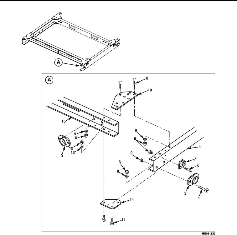
Figure 2.
Pallet Assembly -- Exploded View.
1.
Remove sixteen round head machine screws (Figure 2, Item 1) with hex nuts (Figure 2, Item 2) securing the
eight clearance indicating reflectors (Figure 2, Item 3) to the front pallet (Figure 2, Item 4), rear pallet (not
shown), right side pallet (not shown) and left side pallet (Figure 2, Item 15). Remove reflectors (Figure 2,
Item 3).
2.
Remove eight hex head cap screws (Figure 2, Item 5) with self-locking nuts (Figure 2, Item 6) securing
the four tie down mounts (Figure 2, Item 7) located on the front pallet (Figure 2, Item 4) and rear pallet (not
shown). Remove tie down mounts (Figure 2, Item 7).
0014 00-3