0014 00
TM 1-1730-213-13&P
DISASSEMBLY CONTINUED
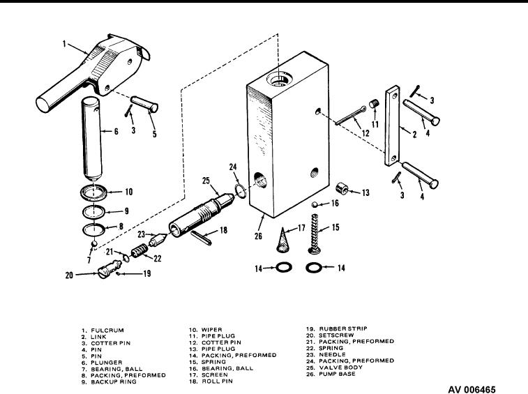
Figure 2.
Pump Assembly.
4.
Drain the hydraulic luid through the pump passage. Remove reservoir ill plug to speed up low of luid.
5.
Remove the fulgrum (Figure 2, Item 1) by disconnecting links (Figure 2, Item 2) and pins (Figure 2, Item 4).
6.
Remove plunger (Figure 2, Item 6), pipe plug (Figure 2, Item 11), cotter pin (Figure 2, Item 12), and ball
bearing (Figure 2, Item 7).
7.
Pry out wiper (Figure 2, Item 10), backup ring (Figure 2, Item 9), and preformed packing (Figure 2, Item 8).
8.
Remove packing (Figure 2, Item 14), spring (Figure 2, Item 15), screen (Figure 2, Item 17), and ball bearing
(Figure 2, Item 16).
9.
Unscrew the valve assembly and press out roller pin (Figure 2, Item 18).
10. Remove setscrew (Figure 2, Item 20), preformed packing (Figure 2, Item 21), spring (Figure 2, Item 22), and
needle (Figure 2, Item 23).
11. Remove preformed packing (Figure 2, Item 24), from valve body (Figure 2, Item 25).
0014 00-2

