0011 00
TM 1-1670-260-12&P
__________________________________________________________________________________________
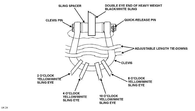
g. Rig Shackle Assembly (Figures 1 and 4)
NOTE
During shackle assembly rigging and subsequent recovery
flight all light weight slings and tie-downs attached to the
main rotor blades are to be attached to the clevis part of
the shackle assembly, while the heavy weight black-white
sling is on the shackle assemblies sling spacer.
(1) Remove quick-release pin, clevis pin and sling spacer from the clevis of shackle assembly. (10,
Figure 1 and Figure 4)
(2) Install free sling eye from yellow/white sling attached to the 2 o’clock position blade retention
assembly onto the clevis part of the shackle assembly.
(3) Place free sling eye from yellow/white sling attached to the 4 o’clock position blade retention assembly
onto the clevis part of the shackle assembly.
(4) Install free sling eye from yellow/white sling at the 10 o’clock position blade retention assembly onto
the clevis part of the shackle assembly.
(5) Place free sling eye from yellow/white sling attached to the 8 o’clock position blade retention assembly
onto the clevis part of the shackle assembly.
(6) Place the midpoint of both adjustable length tie-down slings attached to the topside of the blade
sleeves onto the clevis part of the shackle assembly.
Figure 4. Rigging Shackle Assembly
0011 00-10


