TM 1-1670-260-12&P
0011 00
__________________________________________________________________________________________
CAUTION
Ensure that the sling spacer is installed when the
shackle assembly is assembled.
(7) Place double eye end of heavy weight black/white sling (11), Figure 1, View A, to shackle assembly
(Figure 4) and secure shackle assembly as follows:
(a) Insert sling spacer from shackle assembly into the double eye end opening of heavy weight
black/white sling.
(b) Align the holes in the shackle assembly clevis with hole in sling spacer.
(c) Once holes are aligned, insert clevis pin through holes in shackle assembly clevis and sling spacer.
(d) Insert quick-release pin through hole in base of the clevis pin to secure the clevis pin in the clevis.
h. Carefully lay the rigged shackle assembly on the crossbar assembly with the sling spacer facing up, and move
sling to the side that the recovery helicopter will approach from for easy access during the recovery helicopter
hook-up procedure covered in Paragraph 10 of this WP.
8. Install Tail-Boom Rigging (Figures 1 and 5, and Table 3)
a. Connect one end of blue/white sling (12), Figure 1, View A, to one end of box link assembly (13).
(1) Secure sling (12) to box link using box link pin and quick-release pin. (View F)
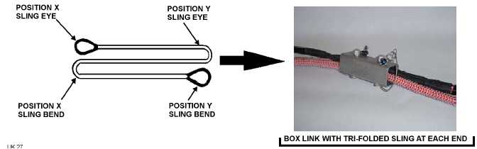
b. Fold a red/white sling (14) into thirds. (Figure 5)
Figure 5. Tri-Folded Sling
c. Using Figure 5 as a guide, connect the Position X sling bend and sling eye from sling (14), Figure 1, View A,
onto the free position of box link assembly (13).
(1) Secure sling (14) to box link using box link pin and quick-release pin. (View F)
d. Using Figure 5 as a guide, connect the Position Y sling bend and sling eye from sling (14), Figure 1, View A,
onto a box link assembly (15).
(1) Secure sling (14) to box link using box link pin and quick-release pin. (View F)
e. Fold a second red/white sling (16) into thirds. (Figure 5)
0011 00-11