TM 1-1500-204-23-5
(7) Keep vise jaws covered with soft metal
jaw caps.
2-3. Propeller Theory. The aircraft propeller consists of
two or more blades and a central hub to which the blades
are attached. Each blade of an aircraft propeller is
essentially a rotating wing. As a result of their
construction, the propeller blades produce forces that
create thrust to pull or push the airplane through the air.
The power needed to rotate the propeller blades is
furnished by the engine. The propeller is mounted on a
shaft, which may be an extension of the crankshaft on
low-horsepower engines; on high-horsepower engines, it
is mounted on a propeller shaft which is geared to the
engine crankshaft. In either case, the engine rotates the
air foils of the blades through the air at high speeds, and
the propeller transforms the rotary power of the engine
into thrust.
2-4. Propeller Model and Blade Designation.
Propellers are identified by stamping the propeller hub
with the serial number, model number, production
certificate number, and the number of times the propeller
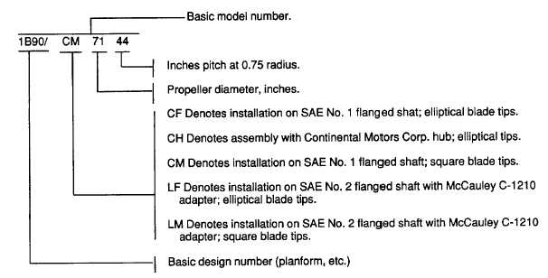
has been reconditioned. The complete model number of
the propeller is a combination of the basic model number
and suffix numbers to indicate the propeller diameter and
pitch. An explanation of a complete model number, using
the McCauley 1B90/CM propeller, is vided in table 2-1.
a. Hartzell Constant-Speed Propeller. The Hartzell
constant-speed propeller uses a hydraulic piston-cylinder
element, as shown in figure 2-1, to control the pitch of the
blades. When the engine speed is below that selected by
the pilot, the governor pilot valve directs governor oil
pressure to the propeller. This pressure forces the
cylinder forward, compressing the feathering spring, and
reducing the propeller pitch. When the engine speed is
above that selected by the pilot, the governor opens the
oil passage to allow the oil in the propeller cylinder to
return to the engine. The feathering spring and the
counterweight force cause the blades to rotate to a higher
pitch position. (See figure 2-2).
b. Turboprop Propeller. The turboprop propeller is
operated by a gas turbine engine through a reduction gear
assembly. The turboprop fuel control and the propeller
governor are connected and operate in coordination with
each other. The power lever directs a signal from the
cockpit to the fuel control for a specific amount of power
from the engine. The fuel control and the propeller
governor together establish the correct combination of
rpm, fuel flow, and propeller blade angle to create
sufficient propeller thrust to provide the desired power.
Table 2-1. Propeller Model Number
Number
Explanation
2-3


