
TM 1-1500-204-23-11
(1) Thermocouple Placement. Control thermo-
the heat source does not touch the object being
couples must be placed properly to measure and
heated. Electricity is used to produce a magnetic
control the amount of heat applied. Placing the ther-
ield which, when placed near a certain type of mate-
mocouples outside the area to be dried and/or cured
rial called a receptor (usually magnetic) causes it to
will affect the quality of the repair and may cause
heat up. This type of heating is not currently used for
under heating, overheating, damage the part, and/or
composite repairs; however, research is underway to
create a ire hazard. See paragraph 6-19.e.4 for
add receptors to adhesives with the goal of develop-
thermocouple placement. See paragraph 6-18g for
ing a fool-proof way to cure composites. Technically,
thermal survey. If a thermal survey was conducted,
induction heating relies on induced electrical currents
the control thermocouples must be placed the same
within the material to produce heat. The basic com-
during the cure as they were during the survey.
ponents of an induction heating system are an AC
power supply, induction coil, and work piece (material
(2) On Aircraft Repairs. Aircraft and hangars
to be heated or treated). The power supply sends
are often classiied as class 1, division 1, (open
alternating current through the coil, generating a mag-
fuel tanks) or class 1, division 2, (closed fuel tanks)
netic ield. When the work piece is placed in the coil,
hazardous areas because fuel and/or fuel vapors
the magnetic ield induces eddy currents in the work
may escape and be ignited by unprotected electrical
piece, generating localized heat without any physical
devices. Hot bonders, portable heat sources, and
contact between the coil and the work piece.
other electrical equipment used on aircraft should
be designed for use in these areas. Contact your
d. Staging of Parts and Equipment. The aircraft
local safety ofice for guidance. Cure temperatures
or part to be repaired should be placed in an area that
shall not exceed 80 percent of the fuel s auto ignition
is thermally stable and wind free. If this is not possible,
temperature unless the fuel tanks have been properly
a temporary shelter should be erected to protect the
purged, a higher temperature has been approved
area from the elements. The repair location should be
through appropriate safety organizations or a waiver
convenient to electrical power, vacuum source, and
has been granted by the authority having jurisdiction.
compressed air. If the repair location is not within
The auto-ignition temperature is the temperature at
easy reach of shop air and electricity, a generator
which fuel can spontaneously ignite without a lame or
and air compressor will be needed.
spark. The auto-ignition temperatures listed on MSDSs
can vary depending on test method, fuel formulation,
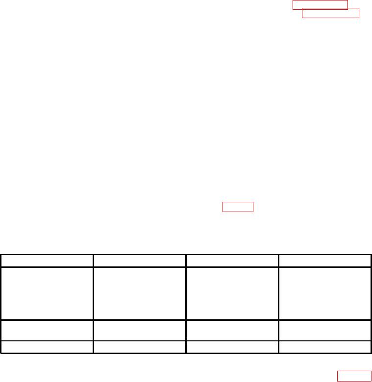
and fuel batch. The maximum cure temperatures
e. Safety Issues. Failure to follow the general
listed in table 6-4 were developed from guidance in
safety requirements in the following paragraphs may
the National Fire Protection Handbook.
result in damage to the part or injury to personnel.
Maximum Cure Temperatures on Aircraft
Fuel Grade
Fuel
Auto-Ignition Temp ( F)
Max.Cure Temp ( F)
JP-8
JP-8+100
JP-6
Kerosene
440 to 475
365
JP-5
Jet A
Jet A-1
JP-4
Blend of Kerosene and
470 to 480
390
Jet B
Gasoline
825 to 960
660
Gasoline
AVGAS
(3) Hazardous Fumes. During material cure,
Thermocouples may be reused. Welded thermocou-
ples shall be used when available. See Chapter 3
hazardous fumes may be emitted. Ensure proper
for thermocouple descriptions and local manufacture
ventilation exists and Personal Protective Equipment
information.
(PPE) is worn as directed by the local safety ofice.
(a) Inspection Prior to Use. Perform the fol-
(4) Thermocouples. Proper
thermocouple
lowing inspection steps prior to each use:
selection, inspection prior to use, and correct place-
ment is necessary to ensure a properly cured repair.