
TM 1-1500-204-23-11
cure to control the heat. These must be
placed around the patch perimeter (out-
side the bondline). Use these as con-
Failure to electrically insulate the thermocou-
trol TCs on the hot bonder or tempera-
ples by placing lash break tape under them
ture control equipment. Be sure to place
may result in a condition known as "cross-talk"
the control TCs in the exact same loca-
and prevent the hot bonder-controller from
tion when performing the cure. Ensure
functioning properly.
TCs are installed away from the vacuum
port. See paragraph 3-3.i for TC infor-
(b) Place TCs in the bondline area on a
mation.
3 to 4 inch grid or strategically place
the TCs over suspected heat sinks
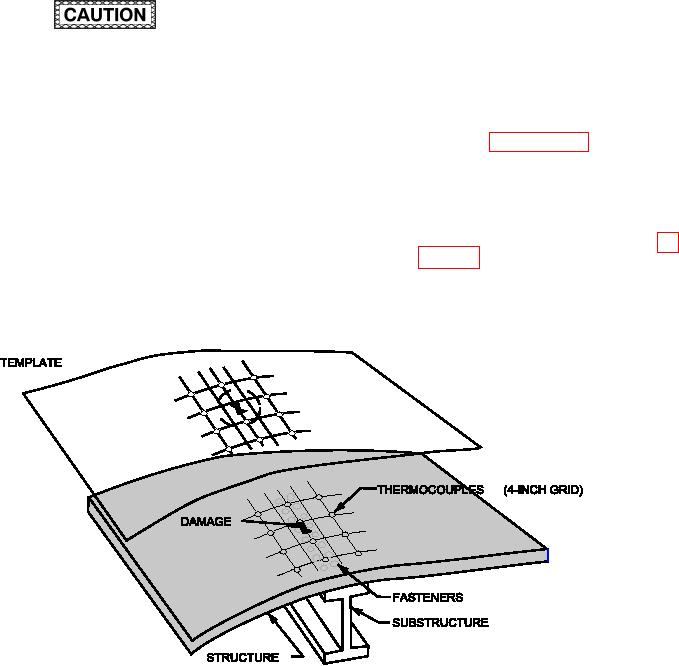
(d) Using clear Mylar ilm or other template
(i.e., stringers, spars, ribs, bulkheads,
material, create a map of the part, heat-
longerons) and hot spots. Place lash-
ing device, exact TC locations and pro-
breaker tape below and above the TC
posed patch perimeter as shown in ig-
tips to protect the control unit from elec-
trical shorts.
(c) Place additional TCs in the locations
that would be used during an actual
Figure 6-36. Typical Thermal Survey Setup
(e) Create a simulated patch made of
(g) Position the heat source in the same
appropriate material and temporarily
position and orientation as it will be used
attach it to the repair area. Ensure the
during the actual repair.
simulated patch is in contact with the
underlying structure.
(h) If the repair process requires a vacuum
bag heat blanket cure, set up the vac-
(f)
All TCs directly exposed to a heat lamp
uum bag (with breather, bleeder, peel
(infrared, quartz, and other) must have
ply, caul plates, etc.) exactly as it would
a small piece of metallic foil tape placed
be done during the repair. Apply vac-
over the lash breaker tape on the bare
uum.
ends. The metallic foil tape prevents
direct heating and erroneous readings
of the TCs.