TM 1-1270-476-30
4-212
4-23. DAY SENSOR SHROUD ASSEMBLY REPAIR (cont)
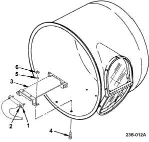
REMOVAL
a. Disconnect connector P2 (1) by loosening
two screwlocks (2).
b. Remove anti-ice CCA A1 (3) by removing
four screws (4), washers (5), and locknuts
(6).
INSTALLATION
c. Remove old corrosion inhibitive coating and
sealing compound from mounting hardware
(para 2-6).
d. Apply corrosion inhibitive sealing and
coating compound to mounting hardware
(para 2-6). Use class 1A application.
e. Install anti-ice CCA A1 (3), using four
screws (4), washers (5), and locknuts (6).
Torque screws to 20 in-lb.
f. Connect connector P2 (1) and tighten two
screwlocks (2).
END OF TASK
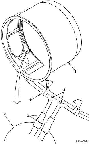
2. THERMOSTATIC SWITCH S1
REPLACEMENT
REMOVAL
a. Cut lacing and tying tape (1) as required to
unsolder wires from thermostatic switch S1
(2).
b. Cut and remove heat shrinkable insulation
sleeving (3), from wires (4) at thermostatic
switch S1 (2).
c. Tag and unsolder wires (4) from
thermostatic switch S1 (2).
d. Grasp thermostatic switch S1 (2) with plier
wrench and twist to remove from shroud
assembly (6).