TM 1-1270-476-30
4-214
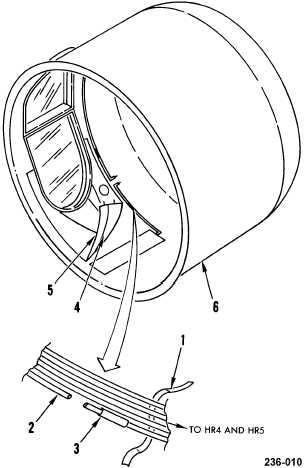
4-23. DAY SENSOR SHROUD ASSEMBLY REPAIR (cont)
3. ANTI-ICE HEATERS HR4 AND HR5
REPLACEMENT
REMOVAL
a. Remove thermostatic switch S1 (2 above).
b. Cut lacing and tying tape (1) as required to
access heater wires (2).
c. Cut wires (2) on far side of splices (3) from
anti-ice heaters HR4 (4) and HR5 (5).
d. Peel anti-ice heaters HR4 (4) and HR5 (5)
off shroud assembly (6).
INSTALLATION
e. Remove old liquid adhesive from shroud
assembly (6) (para 2-6.
f. Apply liquid adhesive to faying surface on
shroud assembly (6) and anti-ice heaters
HR4 (4) and HR5 (5) (para 2-6).
g. Position anti-ice heater HR4 (4) and HR5
(5) on shroud assembly (6) and press into
place. Be sure to work out all trapped air.
CAUTION
When applying heat to heat shrinkable
insulation sleeving, take care to avoid
damaging other components with excessive
heat.
h. Cut heater wires (2) to correct length.
Splice heater wires to shroud wires, using
hot air shrinkable conductor splices (items
58 and 59). Use item 50 to splice three or
more wires. Remove tags.
i. Have installation inspected.
j. Install lacing and tying tape (1) as required.
k. Install thermostatic switch S1 (2 above).
END OF TASK