TM 1-1270-476-30
4-153
4-8. OIP RELAY BRACKET ASSEMBLY REPAIR (cont)
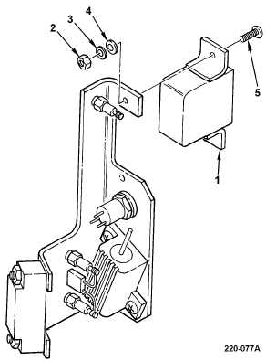
6. RELAY K1 REPLACEMENT
REMOVAL
a. Remove old heat shrinkable insulation
sleeving from wires connected to relay K1
(1) terminals.
b. Tag and unsolder wires from relay K1 (1)
terminals.
c. Remove relay K1 (1) by removing two
locknuts (2), lockwashers (3), washers (4),
and screws (5).
INSULATION
d. Remove old corrosion inhibitive sealing and
coating compound from mounting hardware
(para 2-6).
e. Apply corrosion inhibitive sealing and
coating compound to mounting hardware
(para 2-6). Use class 1A application.
f. Install relay K1 (1) using two screws (5),
washers (4), lockwashers (3), and locknuts
(2).
g. Install new diodes CR1 and CR2 on relay
K1 (1) terminals (4 and 5 above).
h. Install new capacitor C3 on relay terminals
(3 above).
i. Install heat shrinkable insulation sleeving
on each wire and push wire out of way for
soldering.
j. Solder wires to relay K1 (1) terminals and
remove tags.
k. Position heat shrinkable insulation sleeving
over relay K1 (1) terminals.
CAUTION
When applying heat to heat shrinkable
insulation sleeving, take care to avoid
damaging other components with excessive
heat.
l. Using heat gun, shrink heat shrinkable
insulation sleeving around terminals.
m. Have installation inspected.
END OF TASK