TM 1-1270-476-30
4-67
4-5. NIGHT SENSOR ASSEMBLY (NSA) REPAIR (cont)
7. VISUAL MULTIPLEXER ASSEMBLY A33
REPLACEMENT
REMOVAL
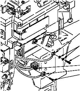
a. Disconnect connector W10P16 (1) from
controller CCA A4 connector J1 (2) by
removing cross-tip screw (3) and two
washers (4).
b. Remove cross-tip screw (5) and disconnect
fan connector A42P1 (6) from capacitor
assembly A41J1 (7).
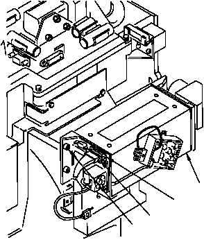
c. Loosen four captive screws (8) and slide
visual multiplexer assembly A33 (9)
outward from NSA to access two
screwlocks (10).
d. Remove visual multiplexer assembly A33
(9) by loosening two screwlocks (10) and
disconnecting connector W10P6 (11) from
connector A33J1.
INSTALLATION
e. Remove old corrosion inhibitive sealing and
coating compound from mounting hardware
(para 2-6).
f. Position visual multiplexer assembly A33
(9) for installation but allow for access to
screwlocks (10).
g. Connect connector W10P6 (11) to
connector A33J1 and tighten two
screwlocks (10).
2
1
4
3
7
6
5
220-319A
8
10
9
11
220-318


