TM 1-1270-476-30
4-65
4-5. NIGHT SENSOR ASSEMBLY (NSA) REPAIR (cont)
6. TRANSISTOR Q1 THRU Q4 REPLACEMENT
NOTE
This procedure is for replacing transistor Q1
(17) and can also be used for replacing
transistors Q2 (19), Q3 (20), or Q4 (21).
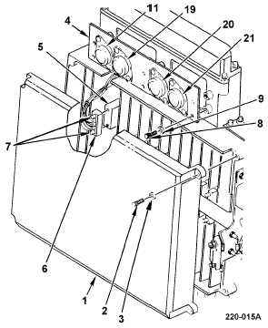
REMOVAL
a. Remove postamplifier cover (1) by
removing four socket head capscrews (2)
and washers (3).
b. Cut lacing and tying tape securing
transistor assembly A38 (4) wires in bundle
between transistor assembly A38 and
postamplifier CCA connector A23J2 (5).
c. Disconnect connector A38P1 (6) from
connector A23J2 (5) by loosening two
screwlocks (7).
d. Remove transistor assembly A38 (4) by
removing six socket head capscrews (8)
and washers (9).
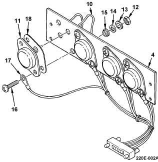
e. Tag and unsolder wires (10) from transistor
Q1 (17) emitter and base terminals.
f. Remove two nuts (12), lockwashers (13),
washers (14), insulator disk (15), screws
(16), and terminal lug (17) securing
transistor Q1 (11), and insulator plate (18)
to transistor assembly A38 (4).
INSTALLATION
g. Install terminal lug (17) on screw (16).
h. Install transistor (11) and insulator plate
(18) using two screws (16), insulator disk
(15), washers (14), lockwashers (13), and
nuts (12). Torque screws (16) to 6 in-lb.
i.
Solder wires (10) to transistor Q1 (11)
emitter and base terminals and remove
tags.