TM 55-1680-320-23 & P
3-39. LIMIT SWITCH DRIVE ASSY - TEST
3 - 3 9
This task covers: Testing
INITIAL SETUP
Personnel Required:
67N, UHl Helicopter Repairer
67T, UH60 Helicopter Repairer
68F, Aircraft Electrical Repairer
Parts/Material:
None
Tools and Test Equipment:
Tool Kit, Aircraft Mechanics
NSN 5180-00323-4692
Shop Set, Intermediate Maintenance
NSN 4920-00-472-4183
Multimeter
Equipment Condition:
Hoist in assembly stand
Limit switch drive assembly removed
Equipment Condition Para:
Task 3-5
Task 2-55
R e f e r e n c e
None
1.
2.
3.
4.
Remove instruction plate by removing screws and
washers.
NOTE
Ensure cam lobes are not engaging
limit switch actuators during testing.
Limit switches are normally closed.
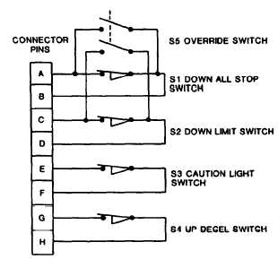
Connect multimeter to pins A and B of drive
assembly electrical connector. There shall be con-
tinuity.
Press down on limit switch S1 actuator. Con-
tinuity shall not be present. Release actuator.
Depress
override switch. If continuity is
not present, replace override switch (Task 3-38).
GO TO NEXT PAGE
3-136


