TM 55-1680-320-23 & P
3-38. LIMIT SWITCH DRIVE ASSY - REPAIR (cont)
3 - 3 8
P.
q.
r.
s.
t.
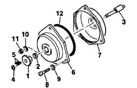
Lubricate packing (12) and install into retainer
(7). Mate retainer with gear (6).
Install gear (6) and retainer (7) onto housing
(20) and secure using screws (8), washers (9,
10) and nut (11).
End play of shaft (27) shall be 0.004-0.008
in. (0.010-0.020 cm). Adjust numbers of
shims (28) installed in step g. to achieve end
play,
Install sprocket (1) and spacer (2) onto shaft
(3). Insert keys (5) and secure sprocket (1)
using retainer (4).
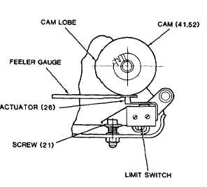
Adjust limit switch actuation setting as folIows:
NOTE
Ensure switch (23) is not actuated
during this adjustment.
(1)
(2)
(3)
(4)
Rotate cams (32, 33) so that limit switch
actuators rest on minimum diameter sur-
face of cams (away from cam lobe).
Connect ohmmeter to pins A and B on
drive assembly electrical connector. Slide
0.045 in. (0.1 14 cm) feeler gauge between
limit switch S1 actuator and cam (32).
Adjust bracket screw (48) until switch
circuit just closes (limit switch on).
Remove 0,045 (O. 114 cm) feeler gauge.
Slide 0.020 (0.050 cm) feeler gauge be-
tween limit switch S 1 actuator and cam
(32). Switch circuit shall be open (limit
switch off).
GO TO NEXT PAGE
3-134