TM 55-1680-320-23 & P
3-38. LIMIT SWITCH DRIVE ASSY - REPAIR (cont)
3-38
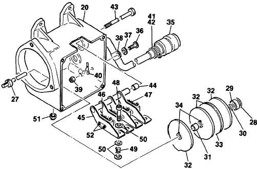
5. Reassembly.
a. Secure limit switches (46, 47) to brackets (45) using screws (52).
b. Install brackets (45) into position in housing (20). Insert shafl (43) through housing, one spacer (44), brackets (45),
second spacer (44) and out opposite side of housing.
c. Secure brackets (45) to housing (20) using screws (48), springs (49), vashers
adjustment will be achieved after limit switch drive assembly is assembled.
d, Feed limit switch elecrical wiring through grommeted hole in housing (20).
secure. Install heat shrink tubing and shrink in place.
(50) and nuts (51). Limit switch
Install electric braid and twist to
e. Using a suitable pin installation tool, install pins into connector (35). Install clamp (41) and secure using screws
(42).
f. Insert electrical wiring from limit switches (46, 47) into clamp (38). Secure clamp to housing (20) using screw
(36), washer (37) and nut (39).
g. Insert shims (28) into housing (20).
h. Lubricate bearing (29) with grease. Assemble bearing, spacers (30, 31) and cam assemblies (32, 33) onto shaft
(27). Install assembly into housing (20). Secure cam assemblies by tightening cam screws (34).
GO TO NEXT PAGE
3-132