TM 55-1680-320-23 & P
2-48. WINCH ASSEMBLY - REPAIR (cont)
2-48
5. Reassembly.
a.
b.
c.
d.
e.
f.
g.
h.
i.
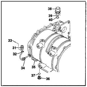
Lubricate packing (37) and install. Install drain
plug (37) and secure using lockwire.
Lubricate packings (39, 40) and install onto
breather assembly (38). Install breather as-
sembly onto winch housing and secure using
lockwire.
Screw thermal switch (34) into winch housing.
Install heat shrink tubing and electrical braid-
ing.
Using a suitable pin installation tool, install
pins into connector (31). Secure electrical
braid and heat shrink tubing in place.
Install connector plug (31) and secure using
clamp (32) and screws (33).
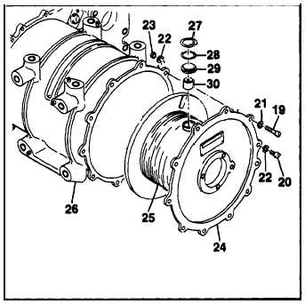
Using a 10-32 screw, install level wind shoe
(30) and retainer (29). Add shims (28) to
obtain end play of .004 to .008 in. between
shoe and retainer. Install retaining ring (27)
into drum assembly. Align matched curved
surfaces.
Position drum assembly (25) near flush with
drum cover assembly (24) by rotating drum
in relation to cover.
Lower assembled drum (25) and cover (24)
into winch housing (26). Ensure proper align-
ment of drum shaft and drum drive gear splines.
Align cover (24) to housing (26) to enable
installation of limit switch drive assembly (7).
Install screws (19, 20), washers (21, 22) and
nuts (23). Torque screws to 12-15 in.lbs
GO TO NEXT PAGE
2-102


