
0098
TM 1-1740-221-13&P&P
CREW PROTECTION SYSTEM (CPS) DASH - (CONTINUED)
10
11
9
12
8
13
7
14
6
15
3
5
4
16
17
2
19
18
20
21
24
23
22
25
1
26
30
29
28
27
SATSCPSab0012
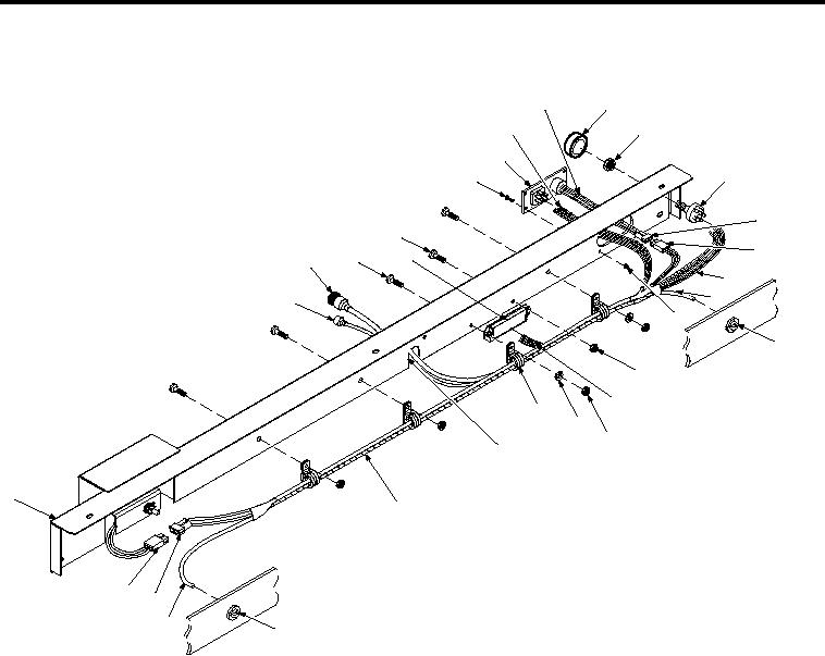
Figure 3.
CPS Dash (Inboard)
END OF TASK
DISASSEMBLY
1. Remove Wiper/Washer Switch (W/W SW):
a. Label and disconnect ive wires (Figure 3, Item 16) from W/W SW (Figure 3, Item 13).
b. Loosen set-screw on side of knob (Figure 3, Item 11) and remove knob from shaft.
c. Remove jam nut (Figure 3, Item 12) on shaft from outboard side of CPS dash (Figure 3, Item 1).
d. Remove W/W SW (Figure 3, Item 13).
2. Remove Heater Control Panel (HCP):
a. Disconnect CPS W/H connector (Figure 3, Item 15) from temperature control diode (TCD) connector
(Figure 3, Item 14).
b. Label and disconnect ive wires from fan control switch (FC SW) (Figure 3, Item 9).
c. Remove four screws (Figure 3, Item 7) and four nuts (Figure 3, Item 19) from corners of HCP
(Figure 3, Item 8).
d. Remove HCP (Figure 3, Item 8).
3. Remove Auxiliary Fuse Block (AFB):
a. Remove tie-straps from AFB wires (Figure 3, Item 21).
00983