TM 1-1730-232-13&P
3-16.6 Hydraulic Ram Replacement, Model 214-706-104-101 (AVUM) - Continued.
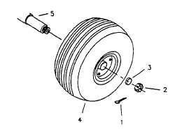
Figure 3-16. Wheel Assembly, Model 214-706-104-101
B. INSTALL
Refer to figure 3-16 and install new or repaired Wheel Assembly as follows'
1.
Install wheel assembly (4) on axle (5), after cleaning and lubricating.
2.
Install retainer (3) and castle nut (2); hand tighten castle nut until snug
3.
Back off castle nut until first slot aligns with hole In axle.
4.
Install cotter pin (1) in slot of nut and hole in axle, and secure by bending both tangs.
5.
Perform service procedure in C below.
C. SERVICE
Service the Wheel Assembly as follows:
1.
Check condition, security, and torque (150-225 inch pounds) on six split rim connector bolts and nuts.
Replace as required H unserviceable.
2.
Check tire pressure with tire pressure gauge for 75 psi (51 7 kPa).
WARNING
Never inflate wheel assembly without first checking wheel locknut torques, to insure wheel
locknuts are tightened to specifications. An assembly with missing washers, bolts, nuts or
improperly tightened locknuts could separate under pressure, causing serious injury or death.
3.
If pressure is incorrect, inflate or deflate tire to 75 psi (51.7 kPa); if pressure is correct, procedure is
completed.
END OF TASK
3-48