*TM 1-1500-204-23-5
Change 3
3-4.1
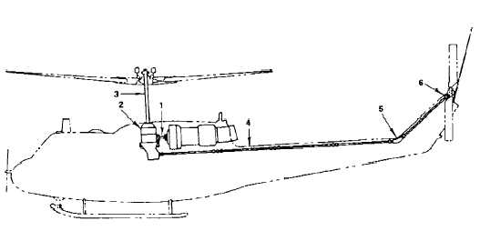
3-4.1 Power Train System. A typical single--rotor pow-
er train system (Figure 3-3.A) consists of a main trans-
mission (main gearbox), a main drive shaft, and a series
of tailrotor drive shafts with two gearboxes. The main
transmission includes input drive with freewheeling pro-
visions if no clutch assembly is required, output drive,
and main rotor mast. The main drive shaft between the
engine and main transmission drives the main transmis-
sion. A series of tail rotor drive shafts with two gearboxes
(transmissions) -- intermediate and tail rotor -- between
the main transmission and tail rotor drive the tail rotor.
1.
Main Drive Transmission
4.
Tail Rotor Drive Shafts
2.
Main Transmission
5.
Intermediate Gearbox
3.
Mast
6.
Tail Rotor Gearbox
Figure
3-3.A. Typical Single--Rotor Power Train System.
a.
Main Drive Shaft. The main drive shaft (Figure
3-3.B) transmits torque from the engine to the main trans-
mission. The shaft is a hollow, statically balanced tube.
In addition to required fittings, bolts, nuts, and washers
are provided with flexible splined or rubber couplings for
installation between the engine and transmission. On
systems using a clutch assembly, the main shaft is at-
tached to the clutch on one end and to the transmission
input drive on the other end. The clutch assembly pro-
vides freewheeling (Figure 3-3.C). On systems not re-
quiring a clutch assembly, the shaft is attached to an
adapter on the engine output shaft on one end and to the
freewheel coupling of the transmission input drive as-
sembly on the other end.
(1)
Clutch Assembly. The clutch assembly al-
lows for a smooth engagement of the engine to the power
train system. The clutch is used to stop possible blade
damage and shaft shearing due to sudden torque load-
ing. Some clutches are designed to let the engine start
and run without the rotor turning. This is very useful for
warm--up and maintenance procedures. Due to the free
power system in all gas turbine engines used by the
Army, a clutch assembly is not needed on aircraft with
gas turbine engines.
The centrifugal clutch assembly is used only with
engines of low horsepower output. When the engine
speed is increased, centrifugal force throws the clutch
shoe against the inner surface of a drum, completing the
drive to the rotor. This type of clutch, because of its slip-
page at low and medium speeds, generates heat, which
is harmful to the life of clutch parts.
(2)
Freewheeling Unit. All rotary--wing aircraft
have a freewheel unit located between the engine and
the main rotor or rotors. Three basic types of freewheel
units are roller, sprag clutch, and overrunning clutch. The
purpose of the freewheel unit is to free the power train
drive system from the drag made by the dead or idling
engine. By doing this the freewheel unit makes autorota-
tion possible. This allows an aircraft to land safely without
engine power. All types of freewheel units generally work