*TM 1-1500-204-23-5
Change 3
3-3
(7)
Keep vise jaws covered with soft metal jaw
caps.
3-3 Principles of Operation and Design Features of
Rotor Systems. The amount of lift available to a rotor
system is determined by many factors. The pilot has
control of the pitch angle of the rotor blades and the
power delivered to the rotor, represented by the rpm. By
controlling the pitch angle of the rotor blades the pilot can
establish the vertical flight of the helicopter. By manipu-
lating the engine rpm control, a constant engine speed
can be maintained regardless of the increase or de-
crease in blade pitch. The engine rpm control is synchro-
nized with the main--rotor pitch control in such a manner
that an increase of pitch increases power and a decrease
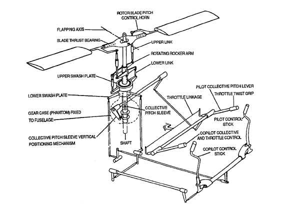
of pitch decreases power. A complete control system of
a conventional helicopter is shown in figure 3-1.
3-4 Helicopter Configurations. There are various he-
licopter configurations. The single rotor and tandem rotor
configurations are explained in the following paragraphs.
a.
Single Rotor. The single rotor configuration, as
shown in figure 3-2, uses one main rotor and a tail rotor
for torque control. The single rotor configuration is the
most common configuration used by Army helicopters.
b.
Tandem Rotor. The tandem rotor configuration,
as shown in figure 3-3, uses two main rotors which rotate
in opposite directions to counteract torque effects. This
configuration is common for large helicopters with spe-
cial mission capability.
Figure
3-1. Helicopter Control System.


