*TM 1-1500-204-23-5
3-4.6
Change 3
Oil temperature and pressure gage readings are
shown by a thermobulb and a pressure transmitter. Most
transmission oil systems provide a heat switch and a
pressure switch which will light caution lights on panels
lettered XMSN OIL HOT and XMSN OIL PRESS (low
pressure) if such conditions occur. Servicing and drain-
ing provisions are provided in the transmission oil sys-
tem. Oil level sight gages are provided on most transmis-
sions; others use the dipstick method. Chip detectors
used in the transmission oil system are similar to those
used on engines.
(5)
Rotor Tachometer--Generator Drive. The ro-
tor tachometer RPM indications are provided by the rotor
tachometer--generator. The tachometer--generator drive
is driven by the main transmission accessory gear train.
(6)
Hydraulic Pump Drive. The hydraulic pump
drive is driven by the main transmission accessory gear
train. The hydraulic pump provides hydraulic pressure
for the flight control servo system. Some helicopters use
two separate flight control servo systems completely in-
dependent of each other. One system is the primary ser-
vo system; it gets hydraulic operating pressure from a
hydraulic pump driven by the main transmission. A sec-
ondary servo system gets hydraulic operating pressure
from a hydraulic pump driven by the engine.
c.
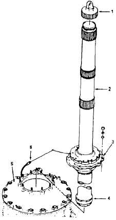
Main Rotor Mast Assembly. The main rotor mast
assembly is a tubular steel shaft fitted with two bearings
which support it vertically in the transmission (Figure
3-3.F). Mast driving splines engage with transmission
upper--stage planetary gear, providing counterclockwise
rotation (viewed from above). The upper bearing retainer
plate has an oil jet fed by an external oil hose. Splines on
the upper portion of the mast provide mounting for main
rotor and control assemblies.
d.
Tail Rotor Drive Shaft. The purpose of the tail
rotor drive shaft is to transmit torque from the main trans-
mission to the tail rotor gearbox (Figure 3-3.G). The shaft
is made up of a series of hollow tubes with provisions for
statically balancing and coupling attachments on each
end. Flexibility in the shaft is provided by splined or rub-
ber couplings. The tail rotor drive shaft is supported by a
series of support bearings and support hanger assem-
blies.
1.
Mast Nut
2.
Mast
3.
Upper Bearing Assembly
4.
Lower Bearing Race
5.
Transmission
6.
Oil Hose for Oil Jet
Figure
3-3.F. Typical Main Rotor Mast Assembly.
e.
Intermediate Gearbox. An intermediate gear-
box is located on the tail boom of the helicopter (Figure
3-3.H). This gearbox provides a specific degree change
in direction of the tail rotor drive shaft with no speed
change. The gearbox assembly consists of a case with
flexible coupling provisions for attaching onto the tail ro-
tor shaft fore and aft. The gearbox is splash--lubricated,
and the case is fitted with an oil filter cap, a vent breather,
an oil level sight gage, and a drain plug equipped with a
magnetic insert. The magnetic insert collects metal par-
ticles coming from inside the gearbox. When there is a
requirement, the metal particles can be collected and
analyzed to determine the condition of the gears and
bearings in the gearbox.


