TM 1-1500-204-23-5
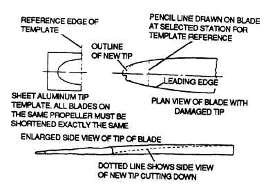
Figure 2-4. Damaged Tip Repair
(e)
Check
three-bladed
propeller
assembly with each blade placed in a downward vertical
position, as shown in figure 2-8.
(2) Suspension method. In the suspension
method, the propeller or part is hung by a cord, any
unbalance is determined by noting the eccentricity
between a disk firmly attached to the cord and a cylinder
attached to the assembly or part being tested. The
suspension method is used less frequently than the
simpler and more accurate knife-edge method.
b.
Aerodynamic
Balancing.
Aerodynamic
unbalance results when the thrust (or pull) of the blades is
unequal. This type of unbalance can be largely
eliminated by checking blade contour and blade angle
setting.
c. Dynamic Balancing. Dynamic unbalance results
when the center of gravity of similar propeller elements,
such as blades on counterweights, does not follow in the
same plane of rotation. Since the length of the propeller
assembly along the engine crankshaft is short in
comparison to its diameter, and since the blades are
secured to the hub so they lie in the same plane
perpendicular to the running axis, the dynamic unbalance
resulting from improper mass distribution is negligible,
provided the track tolerance requirements are met.
d. Blade Tracking. Blade tracking is the process of
determining the positions of the tips of the propeller
blades relative to each other. The blades should all track
one another as closely as possible. The difference in
track at like points must not exceed the tolerance
specified by the propeller manufacturer. Use the
following procedures to check blade tracking:
(1) Mount indicator, which may be a slender
point strip of wood or metal, on a stand, as shown in
figure 2-9. Point of indicator should just touch nearest
part of the blade.
(2) Rotate propeller until next blade is in
same position as No. 1 blade was prior to rotation.
(3) When No. 2 blade does not touch point of
indicator, measure distance from point to point nearest
point of blade. When No. 2 blade is nearer the stand than
No. 1 blade was, move indicator back until it just touches
No. 2 blade.
(4) Rotate propeller again until No.1 blade is
down and measure distance from pointer to blade. With
pointer set to touch nearest blade, the distance to other
blade or blades must not exceed maximum allowable in
overhaul instructions manual for applicable propeller;
otherwise, propeller must be removed for overhaul.
When propeller track is within repairable limits, make
correcting adjustments in accordance with applicable
aircraft or propeller maintenance manual.
2-12. Propeller Installation. Propellers shall be
installed using the applicable maintenance manual.
Preparation for installation is explained by the following
procedures:
a. Depreserve serviceable propellers received from
stock
following
procedure
outlined
in
applicable
maintenance manual.
2-12