
TM 1-1500-204-23-11
In other instances it is a secondarily bonded layer
to expose the foil. The overlap area is the
after the repair patch has already been cured. This
area surrounding the repair area extending
repair procedure is not necessarily applicable to a
out to 1 inch from the repair. A dual action
particular weapon system. The applicability of this
sander with 320 or iner grit abrasive paper
repair depends upon additional factors such as load-
may be used as an alternate to hand sand-
ing conditions and laminate thickness. Consult the
ing. The expanded foil is considered to be
system speciic technical manual or engineering for
exposed when an electrical resistance mea-
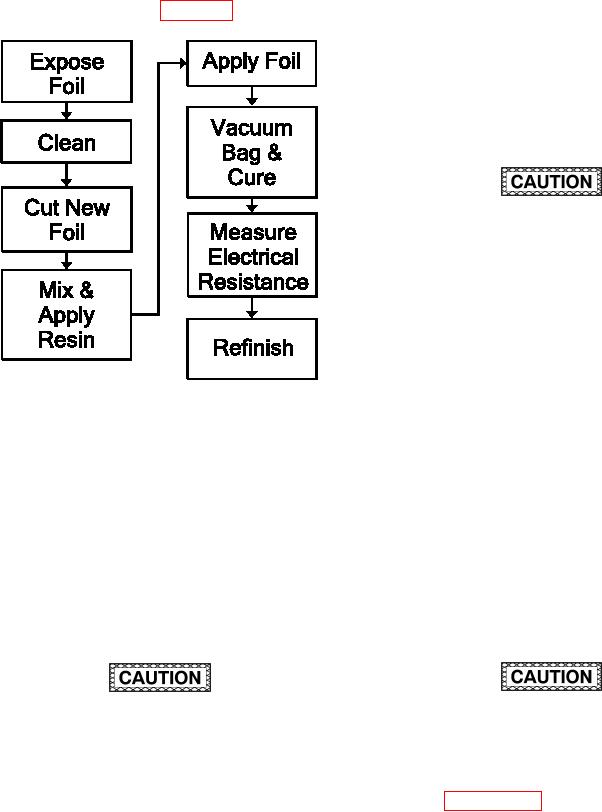
further guidance. Refer to igure 7-70 for the Process
surement of less than 10 milliohms can be
Flow Diagram for Lightning Strike.
achieved by lightly pressing the probe tips
of a milliohm meter on the sanded overlap
area. The probe tips should be at least 1 inch
apart. The reading should be achieved in
several places on the sanded overlap area.
The electrical measurements are for the pur-
pose of assisting in the sanding process only
and veriication is not required at this point.
The expanded foil is extremely thin. Sanding
down into the foil will cause damage to the
expanded foils and will result in high resistance
measurements. Damage caused by over
sanding is not visible to the eye and may
occur without actually sanding through the foil.
Failure to follow these procedures will result
in faulty Electromagnetic Interference (EMI)
shielding/lightning strike protection. In order
to prevent damage, hand sand or use 320
grit abrasive paper on the dual action sander
and make electrical resistance measurements
Figure 7-70. Process Flow Diagram for Lightning
frequently during sanding in order to evaluate
Strike.
the sanding progress. Stop sanding when the
surface is measuring less than 10 milliohms
a. Facilities, Equipment and Materials. The fol-
as described above.
lowing equipment and materials are required: Vacuum
Cleaner, HEPA Filter, Temperature/Vacuum Controller,
(2) Using a ine sanding pad, lightly abrade the
Heat Blanket, Ohm Meter, Dual Action Sander or 90
surface surrounding the repair area for an
degree die-grinder and sanding mandrel, Scissors,
additional 1 inch in all possible directions.
Vacuum Bag Repair Materials Kit, Flash breaker Tape,
This is referred to as the extended repair
Silicon Carbide Abrasive Paper, Sanding Pad, Wiping
area. The repair areas together with the
cloth, Solvent, Peel Ply, Release Film, Spatula, Adhe-
extended repair area make up the entire
sive, Liquid (See System Speciic Technical Manual),
repair area.
Wire Mesh (See System Speciic Technical Manual).
(3) Vacuum sanding dust from repair area.
b. Lightning Strike Procedure.
DO NOT use aluminum lightning mesh on
Do not expose the expanded foil in the
carbon iber composite structure.
extended repair area.
NOTE
(4) Clean the entire repair area with solvent
using a clean dry wiping cloth according to
Processed parts shall be handled using clean
paragraph 6-5. Wipe dry with a second cloth
powder free latex gloves.
prior to the evaporation of the solvent. Wait
(1) Using 240 or iner grit abrasive paper, lightly
30 minutes for solvent to evaporate. Mask
hand sand a 1 inch overlap area enough
off around extended repair area with lash