TM 55-1680-320-23&P
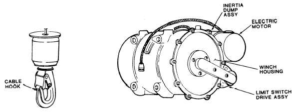
Figure 1-3. Winch Assembly
1-12. Boom Head Assembly.
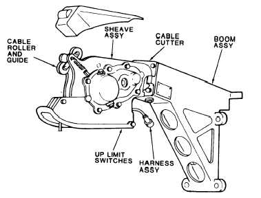
a. The boom head assembly (Figure 1-4) consists of a boom assembly, sheave assembly, dual up-limit switches, cable
roller and guide, brake and clutch assemblies, cable cutter, and two electrical harness assemblies.
b. The boom head is designed to swivel 120 degrees about the boom cable axis, 60 degrees either side of center. The
cable roller assembly and cable guide ensure smooth extension/rewind of the hoist cable. The cable cutter assembly enables
shearing of the cable in emergency situations. Electrical harness assemblies provide electrical power and signals from the
control panel.
Figure 1-4. Boom Head Assembly
1-9


