TM 55-1680-320-23&P
3-148 Change 8
3-43. AUTOMATIC BRAKE ASSY - REPLACE
3-43
This task covers:
Removal and Installation
INITIAL SETUP
Personnel Required:
Equipment Condition:
67N, UH1 Helicopter Repairer
67T, UH60 Helicopter Repairer
Hoist installed in assembly stand
Winch assembly drained
Limit switch drive assembly removed
Parts/Materials:
Equipment Condition Para:
Automatic Transmission Fluid (Item 3,
App. D)
Task 3-5
Task 2-45
Packing (2), NAS1593-152
Task 2-55
Bearing Ball P/N 9306K (Item 141, Fig C-18)
Tools and Test Equipment:
References:
Tool Kit, Aircraft Mechanics
NSN 5180-00-323-4692
Shop Set, Intermediate Maintenance
NSN 4920-00-472-4183
None
1. Removal.
NOTE
Using suitable material, block drum
assembly to prevent rotation when
removing automatic brake assembly.
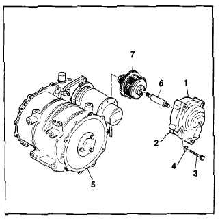
a. Remove pump housing assembly (1) and
automatic brake housing (2) from winch
assembly (5) by removing bolts (3) and wash-
ers (4).
b. Remove shaft (6) from automatic brake
assembly (7).
NOTE
Brake assembly may be difficult to remove
from winch housing.
c. Remove automatic brake assembly (7) from
winch assembly (5).
GO TO NEXT PAGE


