TM 55-1680-320-23 & P
2-54. LIMIT SWITCH DRIVE ASSEMBLY - ADJUST (cont)
2-54
11.
12.
13.
14.
15.
16.
17.
18.
19.
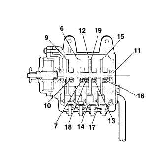
Ensure SW1 and SW2 cam screws (7, 10) are
tight preventing cams (6, 9) from rotating on shaft
(11).
NOTE
The SW3 caution light switch
illuminates the CAUTION lights and
limits maximum hoist speed to 67 feet
per minute.
NOTE
The yellow CAUTION lights are
illuminated from the time the hoist
power switch is turned until the hoist
cable is extended beyond 10 feet.
Move control pendant switch to DOWN. Reel
out hoist cable until 240 feet of cable is extended.
Yellow CAUTION lights shall illuminate.
If yellow CAUTION lights fail to illuminate,
proceed as follows:
a. Loosen SW3 switch cam (12) by loosening screw (18).
b. Adjust cam (12) until cam just actuates SW3 switch (14). Tighten screw (18).
Move control pendant switch to UP.
Reel in hoist cable until cable hook is within 10 feet of full stow. Yellow
CAUTION lights shall illuminate.
If yellow CAUTION lights fail to illuminate, proceed as follows:
a. Loosen SW3 switch cam (19) by loosening screw (13).
b. Adjust cam (19) until cam just actuates SW3 switch (14). Tighten screw (13).
Reel cable out, then in to check adjustment of switch SW3 (14), Ensure illumination of CAUTION lights. Repeat
steps 12 through 15 until adjustment is correct.
Install hook assembly if removed (Task 2-58). Slowly move control pendant switch to UP. Reel in hoist cable until
cable hook is within one foot of up-limit actuator assembly.
Loosen SW4 switch can (15) by loosening screw (16).
Adjust cam (15) until cam just actuates SW4 switch (17). Tighten screw (16).
GO TO NEXT PAGE
2-114


