
0075
TM 1-1740-221-13&P&P
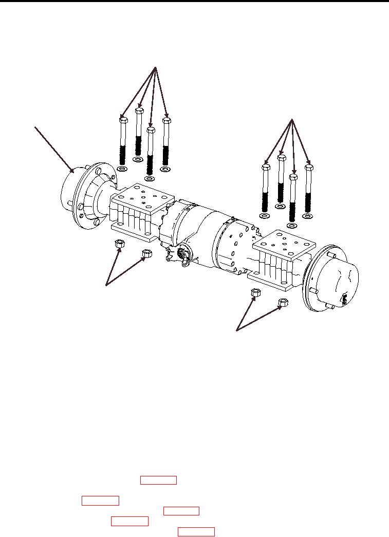
AXLES (FRONT AND REAR) - (CONTINUED)
REAR AXLE
2
2
1
3
3
WP0066F2
Figure 2. Rear Axle (Removal and Installation)
WARNING
Use extreme caution when lifting heavy components. Never permit any part of the body to be
positioned under these components being lifted or suspended. Use suitable lifting equipment
for heavy components. Failure to follow these instructions can result in serious injury or death.
1.
Using a hoist and sling raise the replacement rear axle assembly and place on the axle jacks.
2.
Using axle jacks roll the rear axle assembly under the vehicle through the wheel housing.
3.
Position the rear axle assembly under the 8 mounting bolts (Figure 2, Item 2).
4.
Raise the rear axle assembly allowing the mount bolts to align with the axle mount holes.
5.
Install 8 axle-mounting nuts (Figure 2, Item 3) 4 on each end of the rear axle. Torque nuts to 390-410 ft. lbs..
6.
Install rear shocks on lower mounts (WP 0093).
7.
Remove axle jacks.
8.
Connect brake lines (WP 0084) to axle brake manifold and secure.
9.
Install rear drive shaft (rear axle end only) (WP 0079).
10.
Service rear axle assembly (WP 0076).
11.
Perform rear brake system bleeding procedure (WP 0084).
00754