
TM 1-1730-227-13&P
STANDARD AIRCRAFT MAINTENANCE TRAILER
PART NO. 4920-EG-081 NSN 1730-01-086-1653
EQUIPMENT DESCRIPTION AND DATA
EQUIPMENT CHARACTERISTICS, CAPABILITIES, AND FEATURES
Can be loaded and unloaded by sliding load to or from another trailer.
Can be loaded or unloaded by lifting with a fork lift.
Can be towed together with other trailers.
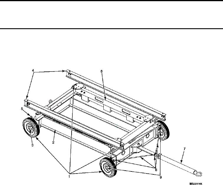
LOCATION AND DESCRIPTION OF MAJOR COMPONENTS
Figure 1.
Standard Aircraft Maintenance Trailer - Major Components.
TIRE AND RIM ASSEMBLY (1)
Consists of a 6.00-9, 6-ply pneumatic tire, a 6.00-9 inner tube, and a 4.00-9 two piece demountable type rim. The rim
assembly is held together by eight bolts, washers, and nuts.
BASE ASSEMBLY (2)
Consists of a welded I-beam assembly and provisions for mounting the front and rear mounting plate, towing bracket
assembly, king pin support assemblies, and the rear corner assemblies.
REAR CORNER ASSEMBLY (3)
Consists of an axle shaft, brake flanges, and rear axle support assembly.
RAIL ASSEMBLY (4)
The rail assembly is comprised of an I-beam which is attached to the pallet assembly (6) and one of two different config-
urations to compensate for different load dimensions. The outer-most mounting position will place the rails 48 inches
apart. The inner mounting position will place the rails 30 inches apart.
The rail assembly is equipped with two rail stop assemblies located at either end of the rail assemblies.
0002 00-1