
0022 00
TM 1-1730-202-13&P
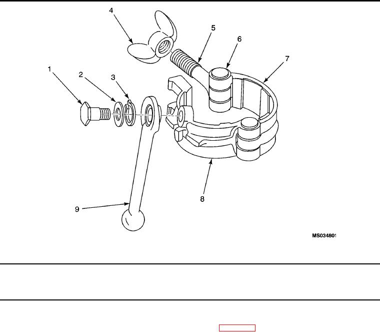
Clamp Assembly.
(1)
(2)
(3)
(4)
(5)
(6)
(7)
ITEM
SMR
PART
DESCRIPTION AND USABLE ON
NO.
CODE
NSN
CAGEC
NUMBER
CODE(UOC)
QTY
CLAMP ASSEMBLY
CLAMP ASSEMBLY
1
XCFZZ
5306-00-282-5192
80049
42A13049
Bolt, Shoulder .............................................................. 1
2
PBOZZ
5310-00-167-0823
88044
AN960-816
Washer, Flat ................................................................ 1
3
XCFZZ
5310-00-167-0677
88044
AN935-816L
Washer, Lock ............................................................... 1
4
XDOZZ
98750
42A13046-3
Wing Nut ...................................................................... 1
5
PBFZZ
5306-00-568-0692
98750
42A13052
Bolt Eye ....................................................................... 1
6
XCFZZ
5320-00-067-9837
88044
AN435-10-20P
Rivet, Solid .................................................................. 2
7
XDOZZ
98750
53C7308
Rear Half Clamp .......................................................... 1
8
XDOZZ
98750
53C7309
Front Half Clamp .......................................................... 1
9
XDOZZ
1730-00-492-3396
98750
42B13048
Handle, Cam ................................................................ 1
END OF FIGURE
0022 00-10