
0031 00
TM 1-1730-201-13&P
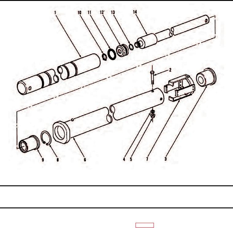
Hydraulic Cylinder Assembly.
(1)
(2)
(3)
(4)
(5)
(6)
(7)
ITEM
SMR
PART
DESCRIPTION AND USABLE ON
NO.
CODE
NSN
CAGEC
NUMBER
CODE(UOC)
QTY
HYDRAULIC CYLINDER ASSEMBLY
HYDRAULIC CYLINDER
ASSEMBLY
1
PBOZZ
3040-00-605-8818
97151
55D21249
Cylinder Assembly, Actuating, Linear ........................... 1
2
XDOZZ
5306-00-180-0145
88044
AN8-43A
Bolt .............................................................................. 1
3
PAOZZ
1730-00-787-1533
80049
55B21265
Cap, Linear Actuating Cylinder .................................... 1
4
PAOZZ
5310-00-045-3298
96906
MS35337-48
Washer, Lock ............................................................... 2
5
PAOZZ
5310-00-877-5795
96906
MS21044N8
Nut, Self-Locking, Hexagon ......................................... 2
6
XDOZZ
3040-00-787-1534
80049
55B21257
Cylinder, Actuator, Linear ............................................. 1
7
XDOZZ
1730-00-909-9404
80049
55C21260
Lock, Barrel, Hydraulic ................................................. 1
8
XDOZZ
Ring, Retaining ............................................................ 1
9
PBOZZ
5365-00-787-1535
80049
55B21263
Bushing, Hydraulic C ................................................... 1
10
PBOZZ
5325-00-281-6623
96906
MS16624-125
Ring, Retaining ............................................................ 1
11
PAOZZ
5331-00-194-3719
88044
AN6227-37
O-Ring ......................................................................... 1
0031 00-6